
0

 veerasiam-g
 Pico Kits
 Pico Accessories
 NVH
NVH
 Overview
 INTRODUCTION
 Features
 Hardware
 Software
 Charging & starting
 Active Diagnostics
 Ignition
 4225A & 4425A
 4823 PicoScope
 Specifications


Pico News





Accelerator Pedal Position
Automotive guided tests
Accelerator pedal position sensor - analog
The purpose of this test is to evaluate the operation of the accelerator pedal position sensor based on the output voltages in relation to pedal position.
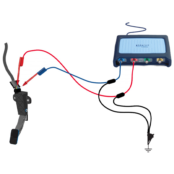
How to perform the test
View connection guidance notes.
Example waveform
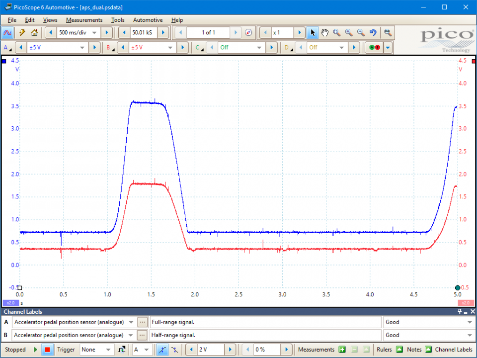
This analogue/digital APP sensor produces an analogue voltage (Channel A, blue trace) and a digital output (Channel B, red trace). The analogue voltage is simply proportional to the pedal position. The digital voltage is a sequence of approximately 12-volt pulses of varying width. The width of each pulse is proportional to the analogue voltage at that time, as shown in Figures 2a,b,c.
In this example, the Accelerator Pedal Position (APP) sensor is of the potentiometer type. It receives two reference voltages from the Powertrain Control Module (PCM), having two ground wires and two signal wires that send a varying voltage back to the PCM relating to accelerator pedal position. The signal voltage sent back to the PCM may vary from manufacturer to manufacturer but will probably never be greater than 5 volts.
Waveform Library
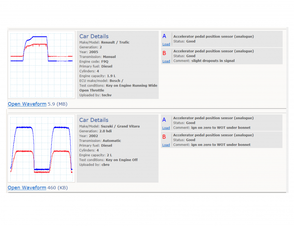
Go to the drop-down menu bar at the lower left corner of the Waveform Library window and select Accelerator pedal position sensor (analogue).
Further guidance
With the increasing level of electronic control and the subsequent decrease in moving mechanical parts it is inevitable that we will see more items being controlled in a "fly by wire manner".
One example of this is throttle control. The majority of vehicles currently being produced no longer use an accelerator cable but instead use an APP in conjunction with an electronic throttle control actuator (ETC) incorporating an electronic throttle motor and a throttle position sensor (TPS).
The APP is quite simply one or, more commonly, two potentiometers attached to the accelerator pedal. As the accelerator is depressed, a voltage signal is sent to the PCM relaying the actual position of the accelerator pedal and thus the driver's physical demand. As a result of this input, the PCM then generates an output to the relevant actuator; in this case the ETC. As previously mentioned, the APP commonly has two potentiometers. These are employed to act as a plausibility test and also to ensure a degree of failsafe operation.
Several methods are used to generate the signal. The great majority use the common 5 volt reference as is used throughout the engine management system. The two most common methods of signal generation are as follows:
Figure 2 : Potentiometer 1 generates a signal of 0.3 to 4.8 volts (red trace in Figure 2) and potentiometer 2 generates a signal of 0.5 to 4.8 volts (blue trace in Figure 2). With an accelerator pedal position of 45 degrees, potentiometer 1 may be outputting a signal of 2 volts and potentiometer 2 a signal of 3 volts, for example.
Figure 3 : Potentiometer 1 generates a signal of 0.3 to 4.8 volts (red trace in Figure 3) and potentiometer 2 generates a signal of 4.8 to 0.3 volts (blue trace in Figure 3). With an accelerator pedal position of 0 degrees, potentiometer 1 may output a signal of 0.5 volts and potentiometer 2 may output a signal of 4.5 volts.
Upon receiving signals in this manner the PCM is able to ensure that the information is correct; for example, if APP angle is 45 degrees, then potentiometer 1 outputs 2 volts and potentiometer 2 outputs 3 volts. If there is any deviation from this then the PCM detects a possible fault and logs a relevant fault code. If one potentiometer track should fail then once again the PCM is able to detect this and run in a failsafe or emergency mode, often raising the idle and limiting throttle operation and lighting the malfunction indicator lamp (MIL). The use of two potentiometers also enables the PCM to monitor the speed at which the accelerator is depressed and closed, the throttle position thus controlling fuelling accordingly.
Should you suspect a fault with the signal, test the wiring from the PCM to the APP.
Ensure that the PCM has good power supplies and grounds where required.
Test the APP (disconnected) with an ohmmeter.
Example pin data
Tested from a Smart Forfour 1.1 petrol 2005 MY.
All figures quoted are approximate and measured by back pinning with ignition on and the multiplug connected.





 Battery Testers
 Diagnostic Chargers
 Service Chargers
 EV Solutions
 Heavy Duty Solutions
 Accessories / Parts
Search
Find your product with fast search. Enter some keyword such as dress, shirts, shoes etc. Or can search by product sku.