0
 Pico Kits
 Pico Accessories
 NVH
NVH
 Overview
 INTRODUCTION
 Features
 Hardware
 Software
 Charging & starting
 Active Diagnostics
 Ignition
 4225A & 4425A
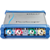
 4823 PicoScope
 Specifications
Current Clamps
Current Clamps

Whenever an electrical current flows in a conductor, a magnetic field is generated around the conductor. The strength of the field is proportional to the current and the direction of the field depends on which way the current is flowing.
A current clamp detects that field and allows you to measure the current without breaking the circuit. For most tests, only one conductor should be measured at a time. If you try to measure current flowing to and from a device (both wires), the magnetic fields will tend to cancel each other out.
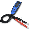
20A / 60A AC (rms) or DC, 20KHz Economy Current Clamp
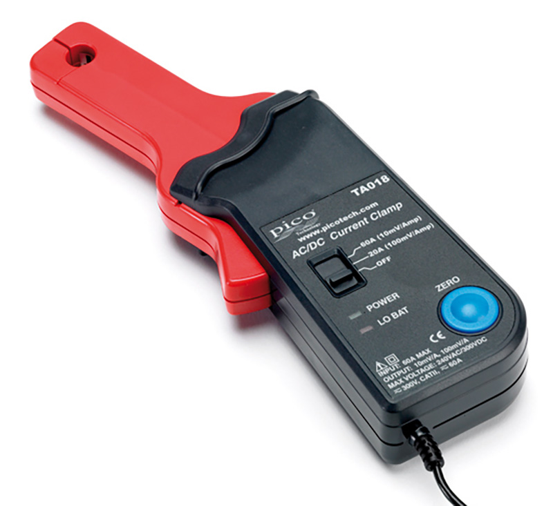
The PICO-TA018 current clamp is ideal for use with PicoScope automotive oscilloscopes for measuring currents between 10mA and 60A. This enables the PicoScope to display current waveforms for fuel injectors and fuel pumps.
The current clamp has two range settings, set by a slider switch on the handle of the probe.
In use there is no need to break into the circuit or disturb the isolation as the opening jaws simply clamp around the current carrying conductor. No electrical contact is required.
These current clamps have been designed for use with PicoScope oscilloscopes and feature additional screening to reduce noise pickup. The Pico TA018 current clamp can either be purchased as an accessory within one of our popular diagnostic kits or individually.
Connecting
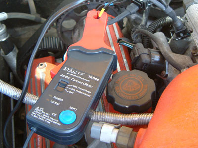
The PICO-TA018 current clamp features a BNC connector and can be plugged directly into a PicoScope.
Once connected to the PicoScope, switch the current clamp on (green LED should light) and then clamp the jaws around the current carrying conductor as shown.
Documentation and Specifications
PICO-TA018 20A / 60A DC Current Clamp User’s Guide
Typical Uses
The PICO-TA018 current clamp simply offers the best value for money without compromising resolution. This current clamp has multiple uses and, with a flexible measurement range from 10 mA to 60 A, the PICO-TA018 clamp is suitable for applications such as:
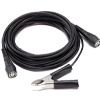
600A AC or DC, 400Hz Economy Current Clamp
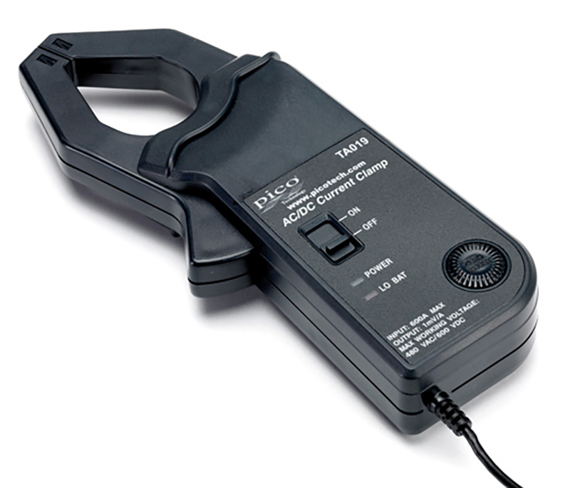
The PICO-TA019 current clamp is ideal for use with a PicoScope automotive oscilloscope to display starter current waveforms, charging currents and for performing quick compression tests.
The current clamp can measure up to 600 A (AC or DC). In use there is no need to break into the circuit or disturb the isolation as the opening jaws simply clamp around the current carrying conductor. No electrical contact is required.
These current clamps have been designed for use with PicoScope oscilloscopes and feature additional screening to reduce noise pickup.
Documentation and Specifications
PICO-TA019 600A AC / DC Current Clamp User’s Guide
Typical Uses
The size and reach of the jaws of this clamp assist you in performing tests easily. Measure the starter motor current of petrol engines, up to 600 amps. Alternator charging systems can also be evaluated (both petrol and diesel engines). The tests are non-intrusive. The PICO-TA019 clamp ensures accuracy with reduced noise levels. The following are examples of tests that can be performed with the PICO-TA019:
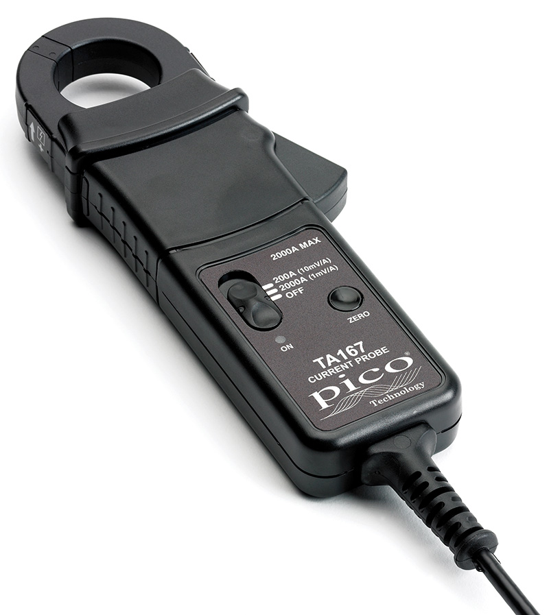
The PICO-TA019 is suitable for monitoring starter current on petrol engines. Diesel engines with their higher compression ratios tend to draw much more current when starting. Please consider our PICO-TA167, 2000A probe, for high-current applications.
Specifications
Electrical Data| (All accuracies stated at 23°C ± 1°C) | |
| Nominal current | 2000 A AC pk max. or DC |
| Measuring range(s) | 2000 A |
| Overload capacity | 2200 A (60 s) |
| Output sensitivity | 10 mV/A and 1 mV/A switchable |
| Accuracy* (0 to 200 A of 10 mV/A) | ± 1% of reading ± 100 mA |
| Accuracy* (0 to 1500 A of 1 mV/A) | ± 1% of reading ± 500 mA |
| Accuracy* (1500 to 2000 A of 1 mV/A) | ± 5% of reading |
| Gain variation | ±0.15% of reading/°C |
| Frequency range | DC to 20 kHz (–1 dB) |
| iRMS x f ≤ 400,000 | |
| Power supply | 9 V alkaline battery PP3, MN 1604 or IEC6LR61 |
| Load impedance (minimum) | > 100 kΩ and ≤ 100 pF |
*Accuracy quoted is for conductor in centre of aperture
General Data
| Conductor size | 32 mm diameter |
| Output cable and connectors | 2 m long coax terminated with safety BNC connector |
| Operating temperature | 0°C to +50°C |
| Storage temperature with Battery removed | –20°C to +85°C |
Instructions
Switch onWhen the probe is switched on and the required measuring range selected, the green LED will illuminate. The LED starts flashing when the battery voltage is too low for normal operation and warns you that it requires changing. This procedure is described below.
Auto power off
In order to save battery life, the probe will automatically switch itself off after approximately 10 minutes. To disable the auto power off function, switch off the probe and switch on while pressing the auto zero button. The red LED will illuminate and the probe will stay on until switched off again
Auto zero
The output zero offset voltage of the probe may change due to thermal shifts and other environmental conditions. Select the required measuring range and then depress the Auto Zero button to null the output voltage. Ensure that the probe is away from any current-carrying conductors while the probe is being nulled.
Current measurement
Battery replacement
The green or red LED will flash when the minimum operating voltage is approached. Use the following procedure:
SAFETY WARNING
Before removing the battery cover, ensure that the probe is disconnected from the oscilloscope and remote from any live electrical circuit.
Unclamp the probe from the conductor, turn it off using the On / Off switch and disconnect the output leads from external equipment. Loosen the captive screw that secures the battery cover. Lift the cover through 30° and pull it clear of the probe body. Replace the battery, re-fit the battery cover and fasten the screw.
Fit only Type 9 V PP3 Alkaline (MN 1604).
30A AC/DC Precision Current Probe
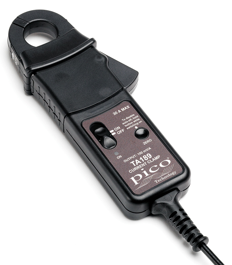
The PICO-TA189 30 A high-precision current probe is for applications requiring non-intrusive current measurement, using closed-loop Hall effect technology to measure both AC and DC current with high stability over long periods of time. Ideal for current leakage monitoring, battery discharge testing, or used in conjunction with an active differential voltage probe such as TA041, it can be used for power quality analysis.
This current clamp has the highest frequency response of the range - 100kHz
Documentation
PICO-TA189 30A Current Clamp User’s Guide
Specifications
| PICO-TA189 30A Precision Current Probe Electrical Specifications (All accuracies stated at 23°C ± 1°C) | |
|---|---|
| Nominal current | 30 A AC peak or DC |
| Measuring range | 30 A |
| Overload capacity | 500 A (60 s) |
| Output sensitivity | 100 mV/A |
| Accuracy | ±1% of reading ± 2 mA |
| Resolution | ±1 mA |
| Gain variation | ±0.01% of reading/°C |
| Frequency range | DC to 100 kHz (0.5 dB) |
| Safety category | CAT III 300 V |
| Power supply | 9 V alkaline battery PP3, MN1604 or IEC 6LR61 |
| Load impedance (minimum) | > 100 k and 100 pF |
| General data | |
| Conductor size | 25 mm diameter |
| Output cable and connectors | 2 m long coax cable with safety BNC connector |
| Operating temperature | 0°C to +50°C |
| Storage temperature with battery removed | –20°C to +85°C |
Current Clamp Feature Comparison
|
|
 |
|
||
|---|---|---|---|---|---|
| Part Number | PICO-TA018 | PICO-TA019 | PICO-TA167 | PICO-TA189 | |
| Current | 20/60A | 600A | 200/2000A | 30A | AC peak or DC |
| Frequency | 20 | 0.4 | 20 | 100 | kHz |
| Overload | 60A | 600A | 2200A (1 min) | 500A (1 min) | AC Peak or DC |
| Sensitivity | 100/10 | 1 | 10/1 | 100 | mV/A |
| Conductor | 9 | 30 | 32 | 25 | mm dia | Please note that this is a rough overview for comparative purposes only. Please refer to the individual devices' specifications. |
Case Studies
|
Jaguar X-type with severe power loss
Engine warning light became illuminated, accompanied with severe lack of power under acceleration after changing gear or when pulling away from rest (evident for approximately 3 weeks). |
|
Injector fault
A 2003 Audi A8 was having a problem with rough running which in turn was causing the engine management light to illuminate. |
|
Battery discharge
Recently I was faced with a customer who had completely given up on the idea of her car ever being fixed. The lady owner of a 2001 Audi A6 1.8 Turbo, explained to me how she has always had problems with the battery discharging. |
|
Cylinder misfire
An intermittent issue of the engine warning light illuminating and fault code “P0302 Cylinder 2 misfire” detected. |
Guided Tests


 Battery Testers
 Diagnostic Chargers
 Service Chargers
 EV Solutions
 Heavy Duty Solutions
 Accessories / Parts
Search
Find your product with fast search. Enter some keyword such as dress, shirts, shoes etc. Or can search by product sku.