0
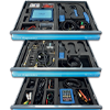 Pico Kits
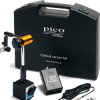
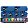
 Pico Accessories
 NVH
NVH
 Overview
 INTRODUCTION
 Features
 Hardware
 Software
 Charging & starting
 Active Diagnostics
 Ignition
 4225A & 4425A
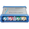
 4823 PicoScope
 Specifications
Pico News


Charging & starting
Pico Technology
Charging Circuits
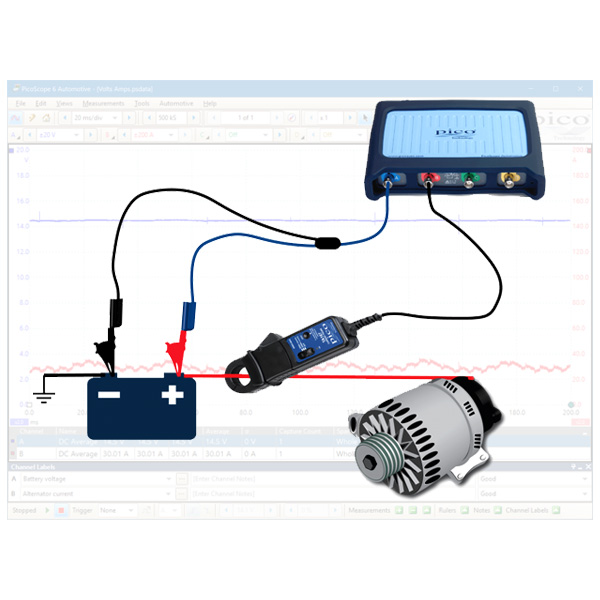
Alternator voltage and current – 12V - 24V
The purpose of this test is to assess the controlled output of the alternator in relation to electrical load on the battery.
How to perform the test
View connection guidance notes.
the vehicle battery terminals.
PicoScope Channel B.
amp clamp before connecting to
the battery positive cable.
Note
The orientation of the clamp relative to the wire will determine whether it has a positive or negative output. If a live waveform does not appear on your screen, or appears to be inverted, try reversing the orientation of the clamp.
Alternator AC ripple – without ECM control
The purpose of this test is to check the rectification of the alternator output voltage, where the alternator output is not regulated by the Engine Control Module (ECM).
How to perform the test
View connection guidance notes.

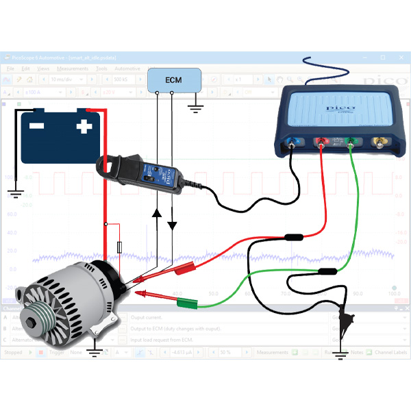
Alternator - smart charge (Ford)
The purpose of this test is to check the command, feedback, and output voltage signals from a Ford-type smart charging alternator.
How to perform the test
View connection guidance notes.
Parasitic drain test – battery
The purpose of this test is to evaluate the level of parasitic current draw from the battery during a vehicle's shutdown phase and sleep periods.
How to perform the test
View connection guidance notes.
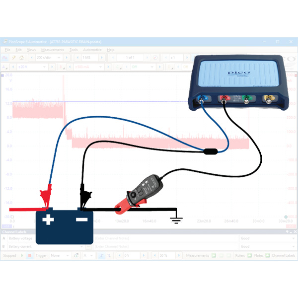
Note
Ensure the test equipment is able to function for an extended time period e.g. current clamp battery condition, scope and pc power supply.
The vehicle must achieve full electrical shut down, with all openings to register as closed with the Body Control Module (BCM), the alarm activated, the emote keys out of range and aftermarket accessories set as per the customer's usual use.
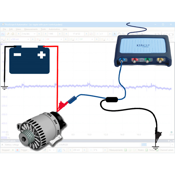
Alternator AC ripple - with ECM control
The purpose of this test is to view the rectification of the alternator output voltage, where the alternator output is regulated by the Engine Control Module (ECM).
How to perform the test
View connection guidance notes.
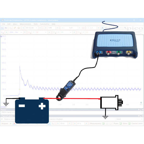
Relative compression - gasoline
The purpose of this test is to compare engine cylinder condition by observing the electrical current drawn by the starter motor during engine cranking.
How to perform the test
View connection guidance notes.
Note
If your engine has a cable operated intake throttle, depress and hold the accelerator pedal during cranking to maximise the air volume drawn in to the engine.
The orientation of the clamp relative to the wire will determine whether it has a positive or negative output. If a waveform does not appear on your screen, or appears to be inverted, try reversing the orientation of the clamp.
Relative compression - diesel
The purpose of this test is to compare engine cylinder condition by observing the electrical current drawn by the starter motor during engine cranking.
How to perform the test
View connection guidance notes.
Note
The orientation of the clamp relative to the wire will determine whether it has a positive or negative output. If a waveform does not appear on your screen, or appears to be inverted, try reversing the orientation of the clamp.


 Battery Testers
 Diagnostic Chargers
 Service Chargers
 EV Solutions
 Heavy Duty Solutions
 Accessories / Parts
Search
Find your product with fast search. Enter some keyword such as dress, shirts, shoes etc. Or can search by product sku.